1.1 PM Plant Editor
Before learning about Pm monitor configuration,it is advisable to take a look at the Plant Editor that is used to describe the structure of the plant that will be used by the Monitor. The interface consists mainly of a tree view there the system components can be dragged. This display will show the component code,its description,and just for the terminals, the reference to the state machine. In the area to the right of the main window are listed the elements that can be "assemble" to draw the system. Below we find the modification window of the selected component data. Let's look the components that we can assemble and how to configure them:
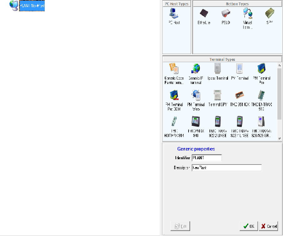
1.1.2 PC HOST
To add a component to the system simply drag it from the list to position that we think is most appropriate. Clearly there are physical link constraints,so you can connect a Net Box only to a Host Pc and a terminal only to a Net Box. Below you can see an example of this structure:
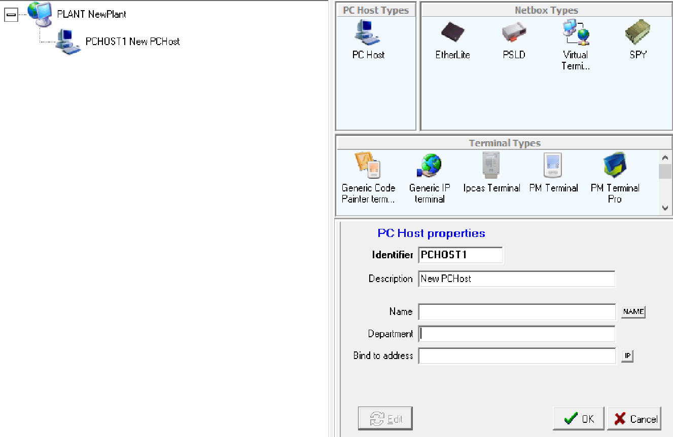
First we drag PC Host,it is the PC on which PM Monitor is activated. Obviously,you must have at least one Host Pc installed. When we add a PC Host to the system in the edit window (bottom right),the configuration parameters of a Host PC will appear. We analyze the various fields:
- Identifier: The host pc code is at the discretion of the user,it must be unique in the system and can be only contain alphanumeric characters.
- Description: is a optional field.
- Name: The host pc name is the name assigned to the computer in the network settings.The NAME button fills the field with the name of the computer you are working on. This can be useful if the system configuration is made on the computer on which the PM Monitor will run. To simplify,just click on the name to see the computer name appear.
- Department: is a descriptive field and can be used to indicate the department that is controlled by that host PC.
- Bind to Address: Indirizzo Ip del computer, cliccando sul tasto ip a destra, lo recupererà in automatico.
Example:
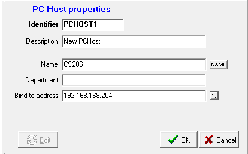
Once completed all fileds that we interest us,click ok to continue. If you need to edit something later,just click on the edit button and at any time we can edit the fields.You can define,and then install,more PC Host and they can work simultaneously.However,you can't activate multiple instances of PM Monitor on the same PC.
1.1.3. NETBOX
Netbox are hardware and software that allows connection between PM Monitor and terminals. Each plant must have at least one netbox selected from those available. Dragging a netbox on the Host Pc to which we will link it to the edit window will display the specific configuration parameters of the selected netbox. In the example you can see the configuration of a netbox Etherlite. Let's put it in our example:
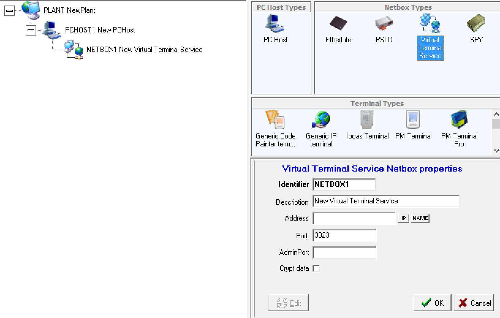
Netbox configuration has some parameters common to all models. They are:
- Identifier: This is netbox code and is at the discretion of the user. It must be unique in the system and can only contain alphanumeric characters.
- Description: It is a description and is an optional field.
Let's now see the parameters for each model:
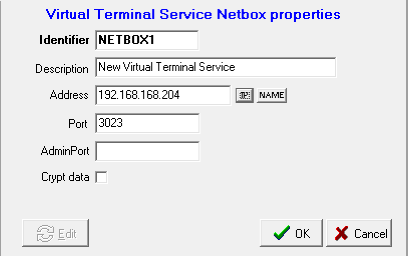
Virtual Terminal Service:
- Address: Ip address assigned to the terminal,alternatively,the name of the PC is also sufficient.Again,just click on IP or NAME to complete the field.
- Port: Socket port of the TCP/IP protocol used for communication.
- AdminPort: optional.
- Crypt data: Encrypt data if there is a need to ensure data protection.
Etherlite:
- Address: Static IP address assigned to the Etherlite.
- Port: Socket port to the TCP/IP protocol used for communication. it must be the same on wireless terminals.
- Status check interval: Preset to 5000 milliseconds.
PSLD:
- Com Port: Enter the serial port number to which the host is to connect:1= COM1 , 2 = COM2.
- RTS Mode: Operating mode depending on the SO.
- Max Terminal Number: Numbers of terminals that are interrogated by the adapter at each polling phase.
- Polling Interval: Milliseconds interval between a polling cycle and the other.This parameter must be calibrated according to the number of terminals and the connection type.It is advisable to enter 80 as the value from which to start.
SPY:
- Config:
- Max terminal number: Maximum number of terminals that are interrogated by the adapter at each polling stage.
- Polling interval: Milliseconds interval between a polling cycle and the other.This parameter must be calibrated according to the number of terminals and the connection type.It is advisable to enter 80 as the value from which to start.
Here's how our virtual terminal service is configured in our example:
1.1.4. TERMINALS
Terminals is the interface of data collection system to the user. Each plant must have at least one terminal selected from those available.Dragging a terminal on the netbox to which we must link it to the edit window will appear on the terminal configuration parameters.
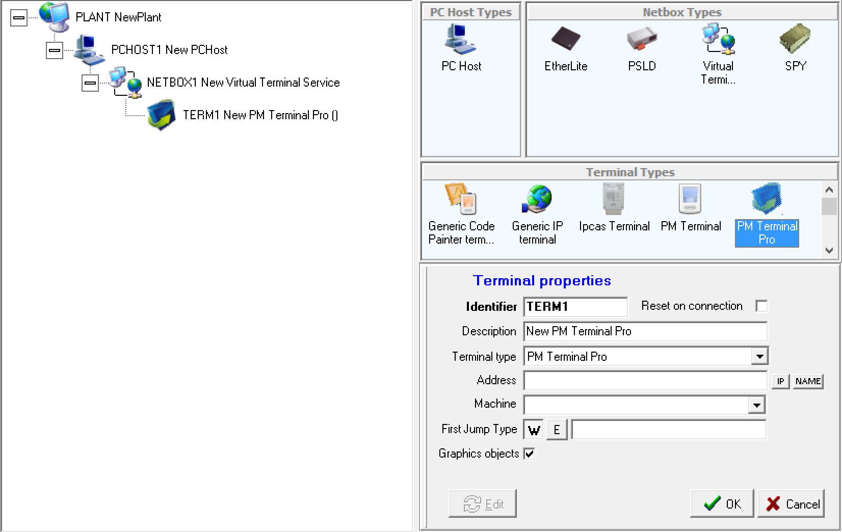
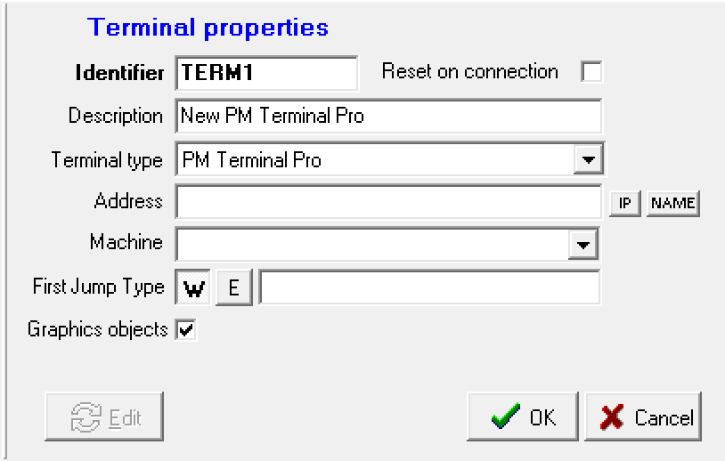
The fields to be filled for each terminal are as follows:
- Identifier: Is the terminal code and is at the discretion of the user. It must be unique in the system and can only contain alphanumeric characters.
- Description: Is a description and a optional field.
- Terminal Type: Is the terminal type.initially it is set based on the dragged object.You can then change this by changing this filed.
- Address: Is the address of terminal.In the case of TMC terminals is the net address 92.For other terminal types is the IP address.
- Machine: Is the state machine associated with terminal.
- First Jump Type: The type of statement that will execute by the machine, if set to W, will wait for a user input because it is wait state, and if set E will execute the first statement without waiting for any input.
1.1.5. MENU
Now let's go to the description of the PM Plant editor menu.
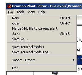

The menu File contains the commands to create a new system,load a file and save it.Additionally,this menu contains functions to add a previously saved system (merge XML file to current plant) to the current system and to save the list of terminal models. The import-export entry allows you to export a representation of the implant in HTML format and import or export to a specific database the PC host,netbox,terminals,machine states and terminal models in the plant editor.
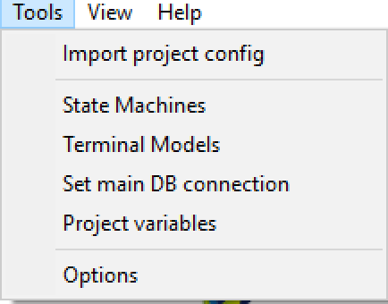
From menu Tools, This menu accesses the state machine configuration templates, the list of supported terminal models,and the option mask. In the PM plant editor options,you must configure the path of the file that is pleasing to the terminal models. An option useful in system editing is "Enter automatically in the edit mode on node selection" that allows you to enter the modification state of the component parameters when selecting the component. You can import the project configurations and view the project variables of our project.

The menu View allows us to access at option of diplaying the parameter settings of the system components.
![]()
The toolbar contains buttons to create a new system,open a plant file,save the current system, and enable or disable the component parameter edit window.
Created with the Personal Edition of HelpNDoc: Write eBooks for the Kindle